1 INTRODUCTION
2 ACTIVE SOIL PRESSURE
2.1 Active wedge
2.2 Surcharge
3 THRUST BEHIND WALL
3.1 Active soil thrust behind wall
3.2 Maximum thrust
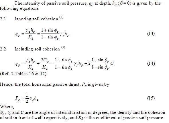
4 PASSIVE SOIL PRESSURE IN FRONT OF WALL
4.1 Ignoring soil cohesion (2)
4.2 Including soil cohesion (2)
5 DESIGN OF RIGID RETAINING WALLS
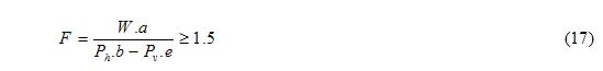
5.1 Stability against overturning
5.1.1 Ignoring the soil in front of wall
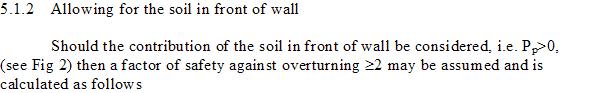
5.1.2 Allowing for the soil in front of wall
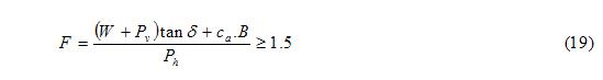
5.2 Stability against sliding
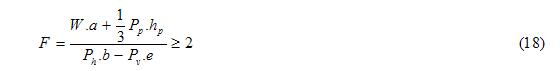
5.2.1 Ignoring soil in front of wall (1)
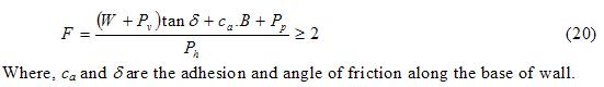
5.2.2 Allowing for soil in front of wall (1)
6 WALL GEOMETRY
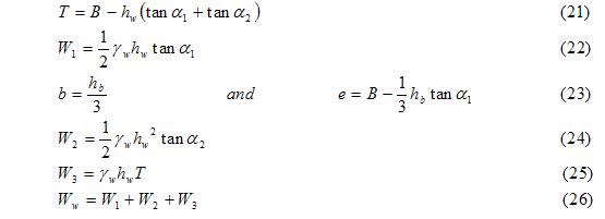
7 WIND LOADING
7.1 INTRODUCTION
7.2 NOMENCLATURE
7.3 THERMODYNAMIC PROPERTIES (3)
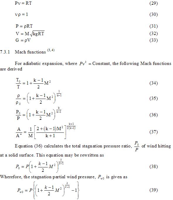
7.3.1 Mach functions (3, 4)
7.3.2 Speed of sound (4)
7.3.3 Wind pressure
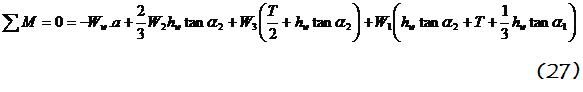
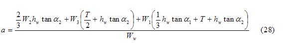
7.4 WIND FORCE
8 RETAINING WALLS COMPUTER SOFTWARE
8.1 INTRODUCTION
8.2 SCOPE OF PROGRAM
8.3 PROGRAMMING LANGUAGES
8.4 SYSTEM REQUIREMENTS
8.5 RUNNING THE PROGRAM
8.6 EXAMPLE OF PROGRAM APPLICATION
8.7 INPUT OF DATA
8.8 PROGRAM OUTPUT
8.9 ANALYSIS OF WALL STABILITY OUTPUT
8.9.1 Ignoring the surcharge loads of the tree
8.9.2 Including the concentrated surcharge weight of the tree
8.9.3 Including the effect of wind
9 CONCLUSION AND RECOMMENDATIONS
GRAVITY RETAINING WALLS
1. INTRODUCTION
The ratio of the soil pressure on the retaining wall to the overburden pressure is known as the coefficient of earth pressure. If the wall is allowed to move forward slightly then the earth pressure on it gradually decreases until it reaches a minimum value. The coefficient of earth pressure is then known as the coefficient of active pressure. If the wall pushes towards the soil, such as pushing against the soil in front, the earth pressure gradually increases until it reaches a maximum value. The coefficient of earth pressure is then known as the coefficient of passive pressure.
In this study, the walls are assumed to be rigid, constructed out of masonry, mass or reinforced concrete. They can fail either by sliding or more usually by overturning. Active soil pressure behind the wall and passive soil pressure in front of the wall are assumed to govern the design. The Surface of soil behind the retaining wall may be horizontal or sloping. Surcharges may be applied as concentrated, uniformly distributed, triangular, trapezoidal or any combination thereof. Trapezoidal surcharges may be analysed as triangular and uniformly distributed surcharges. For simplicity, the soil surface in front of the wall is assumed to be horizontal.
2. ACTIVE SOIL PRESSURE
A procedure to determine the active thrust on a retaining wall is outlined below. Sufficiently accurate values of active thrust, Pa, can be obtained by assuming that the slip surface is a plane (Coulomb’s method) (1)
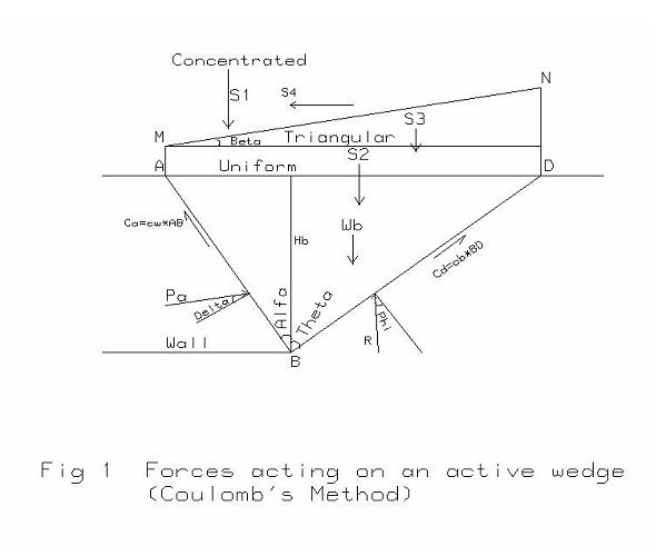
2.1 Active wedge
From the geometry of Fig 1, the following relations may be formed
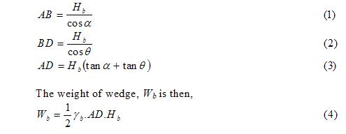
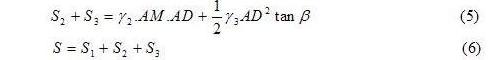
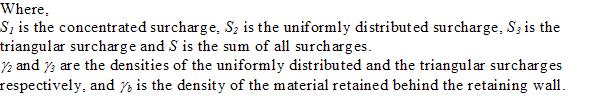
2.2 Surcharge
The surcharges, S shown in Fig 1, may be calculated as follows
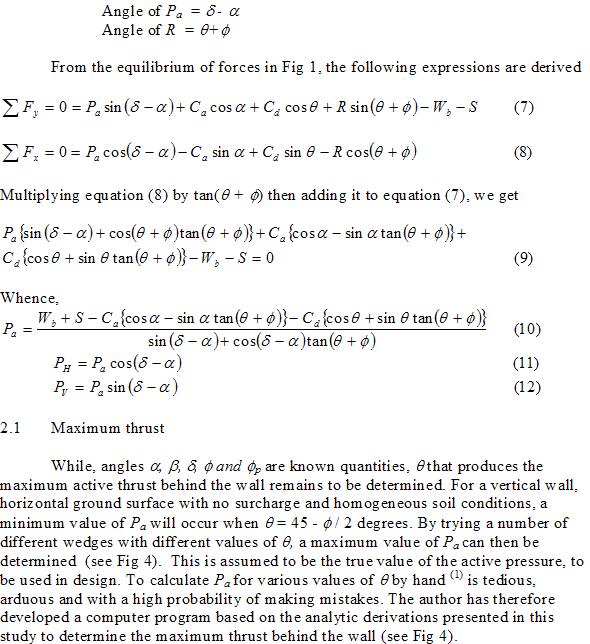
3.1 Active soil thrust behind wall
From Fig 1, the angles of Pa and of R with the horizon are
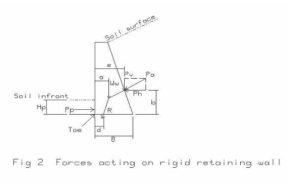
4.1 Stability against overturning
5.1.1 Ignoring the soil in front of wall
The contribution of the soil in front of wall to stability is usually ignored (1) (Pp=0). From Fig 2, the position, d of the resultant R, is determined by taking moments about the Toe as follows

Resistance to sliding is checked by comparing horizontal thrust to maximum base friction and adhesion that may be developed.
5.2.1 Ignoring soil in front of wall
From Fig 3, the following expressions may be derived
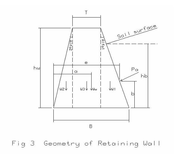
7.1 INTRODUCTION
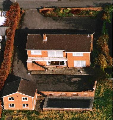
The presence of large trees close to the wall raises serious concerns about the destabilizing effect of severe East winds. Such winds produce transverse shearing forces within the cross section of the stems that will be transmitted from the stems to the backfill behind the wall. The influence of wind forces must therefore be added to the horizontal backfill thrust on the retaining wall.
7.2 NOMENCLATURE
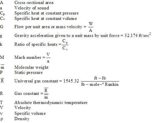
Air will be treated as an ideally compressible fluid. The effect of viscosity is therefore neglected. The most important consequence of viscosity is probably skin friction due to drag in the boundary layer.
The equation of state for a unit mass of air as well as for many other gases over a range of states which includes most engineering applications is accurately represented by the relations (5,6)
7.3.3 Speed of sound (4)
The speed of sound in air at standard conditions is

1. Carter, M.: Geotechnical Engineering Handbook, Pentch Press, Chapman and Hall, London & Plymouth. 1983
2. Reynolds, Charles E and James C Steedman: Reinforced Concrete Designer's Handbook, Ninth Edition, 1981
3. Dr. Helou, Anis; Geometric Design of Supersonic Ramjet Engines. Hewlett-Packard, Series 70 Users' Library, Catalogue No. 75001775, June 1984.
4. Rolls-Royce, Conversion Booklet, Tables, Factors, Definitions and Basic Units; Rolls-Royce Limited, Derby, UK.
5. Building Systems Cost Guide 1981, Robert Show Means Company, Inc.; 100
Construction Plaza, Kingston MA 02364, USA.
6. Keenan & Key: Thermodynamic Gas Tables, USA